Wednesday, June 21, 2017

Dial Lights Completed


Cutting dial light boards from large perf board


Ten right side and ten left side


Dial light lit up

Tuning subchassis ready for installation into radio case


Sunday, June 11, 2017

Pos Ground 6 Volt to Neg Ground 12 Volt

Here is the plan to get the M radio to work on 12 volt negative ground system. Normally the M radio is not polarity sensitive but the vibrator I'm using is. Good thing that a positive and a negative ground vibrators are made... I also (in a previous post) decided to use a bridge rectifier for the LED dial lights so there would not be a polarity issue with them.


Sunday, May 28, 2017

Dial Light LED Solution

Most of the lamp holder's insulating components are trash and these lamps are a bit hard to get to so I decided to come up with a LED solution. All the tuning chassis have been taken apart to clean so one of the rivets were removed. This gave a good mounting screw location to mount the LED boards. Just need to drill and tap for a #8-32 screw. On radios that do not have this rivet removed a clip could be made to hold the LED boards, maybe even using the clips from the lamp holders.

****UPDATE*****

Just did a test fit and the above design did not fit so I went back to the drawing board for a modified layout:


****UPDATE*****
One more try:

****UPDATE*****
Thought I was done but one more try is needed:


Tuesday, May 23, 2017

Recap and Reresistor

Most folks just replace the cow pastures but I decided to replace everything...

 Old components

 Chassis striped

New components


Case Strip & Paint


Cases striped, media blasted, and conversion coated ready for paint

Jig for painting cases

Case painted with silver hammer tone

Packing away cases & covers for protection waiting for assembly


 Antenna receptical

 Painting recepticals


Wednesday, January 4, 2017

Chassis Tear Down

w
w
 Radio #9 ready for tear down

Tubes, vibrator and filter cap already removed
 
 First up is to remove the power lead

 Solder-Wick it and then pull it out

 Then a couple of caps soldered to a lug on the chassis


 Tuning mechanism to chassis ground strap

 Solder-Wick and disconnect strap


 Cut the tone control leads

 Unclip the dial lights

 Remove the control mounting nuts

 Solder-Wick and remove antenna coil connection

 Cut third tone control lead

 Remove tuning mechanism mounting screw

 Remove tuning mechanism

 Remove tone control

 Remove tuning mechanism rear plate mounting nuts

Remove rear plate
 
Solder-Wick and remove the tuning slugs
 
Label tuning slug locations (A, B, & C)
 
 Removing dial pointer


 Removing mechanism bumpers

 Removing push buttons

 Removing bumpers

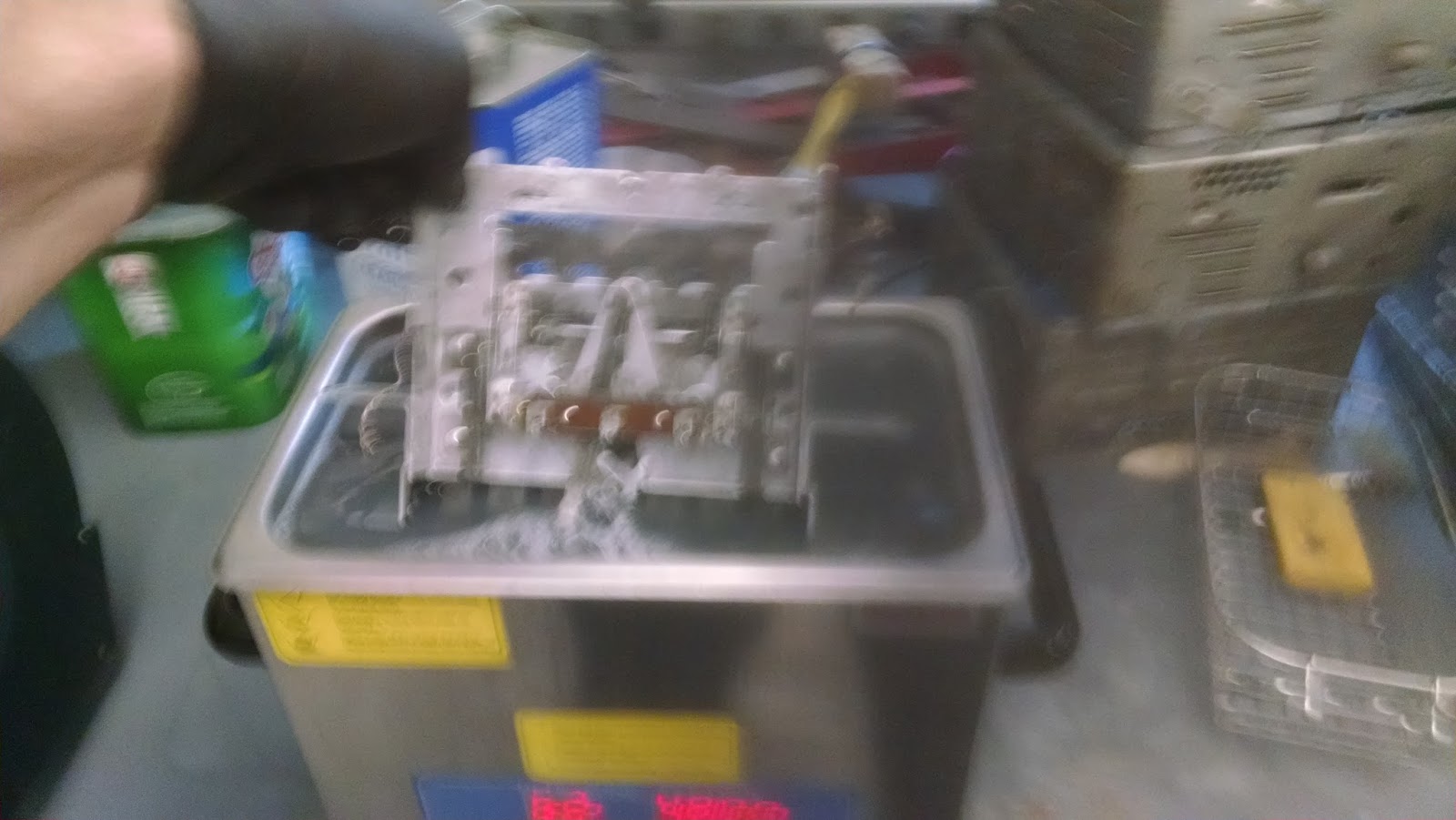
 Tuning mechanism ready for ultrasonic cleaning

 Removing chassis from case

 Removing antenna input connector

 Grinding down rivet that holds the antenna input pad

 Automatic punch works great to p[op out the ritets

 Case ready for paint strip, media blast and painting

 Remove the dial


 Tuning mechanism ultrasonically cleaned