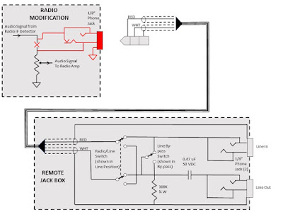
I added a jack on each radio for an adapter box to provide some connectivity to and iPod, Blutooth adapter, or a smart phone. The box also has the capability to play the radio audio through a modern car stereo.
Studebaker M Series Radio S4626/S4627/S4824
Saturday, May 12, 2018
Wednesday, October 25, 2017
Saturday, August 12, 2017
Update on the 6 to 12 Volt Conversion
Tried the Zener diode approach, it did work but the Zener diodes got to hot. I knew there would be a power issue but didn't know how big of an issue it would be not knowing how quick the tube filaments would heat up. Added a power transistor and that fixed the power issue but decided to go the better route of replacing the tubes with 14 volt series and rewind the low to high voltage transformer.
Although labor intensive, rewinding the transformer turned out to be fairly easy. It is unfortunate that the primary winding is under the secondary winding but I have a trick for that...
Although labor intensive, rewinding the transformer turned out to be fairly easy. It is unfortunate that the primary winding is under the secondary winding but I have a trick for that...
First, I remove the transformer from the radio chassis and then remove the outer EMI shield.
After removing the bolts that hold the Es and Is together I use a razor blade to start the process of removing all the Es and Is.
Sometimes it helps to use a thin sheet of metal. Here I use a some flashing.
First E off.
About half done.
All the of the core removed one can see the primary winding, composed of 17 AWG magnet wire.
Remove the outer layers of paper to get to the ends of the wire connections.
Remove the bobbin, more like destroy the bobbin.
Bobbin removed
Start pulling out the primary wire.
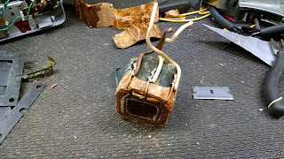
Secondary without the primary.
Primary wire.
All the Es and Is need to be steel wooled to remove most of the varnish so the can lay flat again. Don't go to crazy as we don't want any electrical connection between the laminations, cuz' eddy currents...
Time to start making a new bobbin. I picked cardboard from a small tablet. The tablet's cardboard back was made of two layers so when I soaked it in water they came apart. Made it easier to make a good bobbin of two layers with over lapping seams. I used veneer glue to hold the layers together and clamped all four sides to set the glue. I left it on the form until dry. The form is made from a piece of pine cut to the correct dimensions with two layers of duct tape.
Test fitting the bobbin on the Es.
Checking the clearance between the bobbin and the secondary winding. Before I started this I did a bunch of calculating to determine if the new primary winding would fit.
Starting to wind the primary on the new bobbin.
I used two pieces of 14 AWG wire to space the winding from the edge and started with a "flag", a piece of tape to restrain that end of the wire from pulling out of the form.
first few winding hold the lag in place.
First layer.
Each layer gets a cover of tape.
After second layer I needed a center tap so here is another two flags.
Total of 4 layers. The original winding was 70 turns, to convert to 12 volts I needed twice that for the correct turns ratio and hence voltage. Since I used a smaller gauge wire (20 vs 17) I can get more windings in the same space. BTW 20 AWG is half the cross sectional area as 17 AWG. With four layers I got 140 turns.
Checking fit onto the core. Checking is a good thing.
Now, to put that newly minted primary winding into the secondary winding...
To get it in I had to squish the secondary a little.
Awe, nice and tight!
Now is time to start re-leading the windings.
Windings all done and ready to install the Es and Is
Here we go installing each E, alternating their direction same as they were originally installed.
After installing the Es, install all the Is.
Install the bolts and before completely tightening them give the sides a few little taps with the hammer to seat them all.
Sunday, July 23, 2017
Subscribe to:
Comments (Atom)


